System Model of a Multi-Cylinder SI Engine in Lotus Engine Simulation
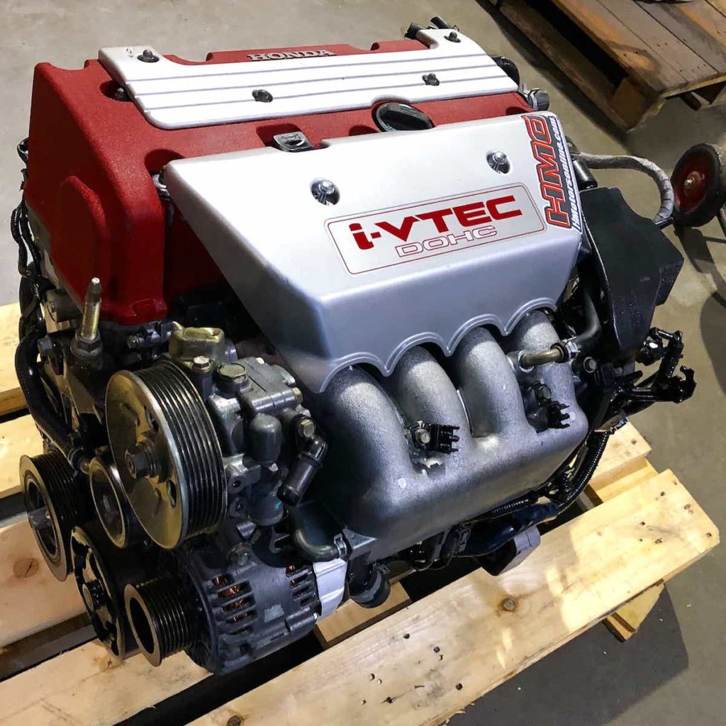
A full system model of the Honda K20A, a 2.0 L naturally aspirated inline-4, built in Lotus Engine Simulation. Air flows through the throttle, intake plenum, ports and valves into four cylinders and out through the exhaust, so volumetric efficiency, torque and power come out of the simulation from 1200 to 8400 RPM.
- Lotus Engine Simulation
- 1D gas dynamics
- Wiebe
- Annand
- Volumetric efficiency
- Honda K20A
- Displacement
- 1998 cm³
- Peak volumetric efficiency
- ~100 %
- Peak gas temperature
- ~3000 K
- RPM at peak power
- ~6000
Full-load sweep of the Honda K20A from 1200 to 8400 RPM.
Overview
A single-zone model only covers the closed-valve part of the cycle, so it cannot say how much air the engine actually breathes. A multi-cylinder system model closes that gap. The throttle, plenums, ports and valves are part of the model, so volumetric efficiency and its effect on torque and power become results instead of inputs.
I built the model in Lotus Engine Simulation (LES) around the Honda K20A, an engine with widely published specifications, and ran it at full load across its whole speed range. Power and torque fall off above roughly 6000 RPM, well short of the published rating, and the gas-exchange results point to the exhaust side of the model as the cause.
- 01
Complete engine system
Throttle, intake plenum, four ports, sixteen valves, four cylinders and a common exhaust plenum, firing 1-3-4-2.
- 02
Full speed sweep
Torque, power, BSFC, BMEP, volumetric efficiency and combustion phasing from 1200 RPM to the 8400 RPM redline.
- 03
Diagnosed shortfall
Constant combustion phasing, falling volumetric efficiency and high exhaust plenum pressure point to a gas-exchange limit.
How the model is built
- 01
Layout
An ambient source and throttle feed the intake plenum, which splits into four intake ports. Each port serves two intake valves, and four exhaust ports collect into one exhaust plenum that discharges to ambient.
- 02
Cylinders and combustion
Each cylinder gets the K20A geometry. A single Wiebe function with A = 6.91 and M = 2 burns about 99.9 % of the charge by the end of the burn duration.
- 03
Heat transfer
The Annand correlation, with separate coefficient sets for the open and closed parts of the cycle, handles convection and radiation to the walls.
- 04
Valves, ports and throttle
Fast-lift polynomial valve curves, the default "good port" flow characteristic and a fixed-discharge-coefficient throttle complete the breathing path.
Engine and model setup
- Engine
- Honda K20A, 1998 cm³ inline-4
- Bore and stroke
- 86.0 mm and 85.9 mm
- Connecting rod
- 139 mm
- Compression ratio
- 11.5
- Valve timing
- IVO 10° BTDC, IVC 50° ABDC, EVO 50° BBDC, EVC 10° ATDC
- Valve lift
- 12.27 mm intake, 10.77 mm exhaust
- Combustion
- Single Wiebe, A = 6.91, M = 2
- Heat transfer
- Annand, LES default coefficients
- Throttle
- 60 mm equivalent bore, Cd = 0.6
Results across the speed range
- Power and torque
- Rise to about 6000 RPM, then both fall
- BSFC
- Fairly flat, rising steeply near the redline
- Volumetric efficiency
- About 100 % at 5400 to 6000 RPM, then drops
- Combustion phasing
- A50 nearly constant at every speed
- Exhaust plenum
- Above 1.4 bar between about 5400 and 7200 RPM
Limits and next steps
- 01
Exhaust plenum size
The exhaust plenum kept the default 2.53 L volume and 100 °C wall, while the real collector is about 0.6 L. Matching it and modeling runners and a collector is the first fix.
- 02
VTEC not modeled
A single set of valve events serves the whole speed range. Representing both VTEC cam profiles would help at high speed.
- 03
Generic, uncalibrated inputs
Port flow, heat transfer and combustion use generic values. Comparing against measured power and torque data would let them be calibrated.